
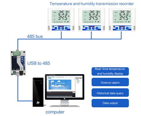
How to wire 485 and analog sensors?
RS485 remote temp and humidity sensor has two-wire and four-wire connections. The four-wire system can only achieve point-to-point communication, which is rarely used now. Nowadays, the two-wire connection method is mostly used. This wiring method is a bus topology. Up to 32 nodes can be connected on the same bus.
RS485 remote temp and humidity sensor wiring specification:
1. The 485 signal line cannot be routed together with the power line. In the actual construction, because the wiring is routed through pipelines, sometimes the construction party directly binds the 485 signal line and the power line together for the convenience of the drawing. Because the strong current has a strong electromagnetic signal to interfere with the weak current, The 485 signal is unstable and the communication is unstable.
2. 485 signal wire can use shielded wire as wiring, or unshielded wire as wiring.
3. You can choose to use ordinary super Category 5 shielded twisted pair or network cable. The wire is generally recommended to choose the standard 485 wire, which is a shielded twisted pair. The transmission line is not a single copper wire like a network cable, but multiple copper wires are twisted together to form a wire so that even if a small copper wire is broken It will not affect the entire use.
4. 485 wiring can be arbitrarily arranged into star wiring and tree wiring with the help of 485 hubs and 485 repeaters. The 485 wiring specification is wiring that must be hand-in-hand. Once the 485 hubs and 485 repeaters are not directly wired into star connection and tree connection, it is easy to cause signal reflection and cause the bus to be unstable.
5. The 485 bus must be grounded.
How to wire the analog temperature and humidity sensor?
The output mode of the analog remote temperature humidity sensor has a current type and voltage type. Whether it is a current type signal or a voltage type signal, it is divided into the four-wire system, three-wire system, and two-wire system based on the number of signal meters and equipment cables. Three types, different types of signal wiring methods are different.
The wire system is a difficult point to understand the analog quantity. Pay attention to the outgoing wire of the equipment that provides the signal. There are several wire systems. The following figure shows the wiring differences between these types of wire systems.
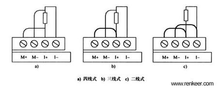
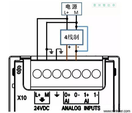
Four-wire system humidity temperature monitor
The four-wire signal means that the signal line and the power line on the equipment providing the signal have 4 lines in total. The signal-providing equipment has a separate power supply, in addition to two power lines, there are two signal lines. The wiring of the four-wire signal is shown in the figure below:
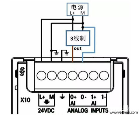
Three-wire system humidity temperature monitor
The three-wire signal means that on the equipment that provides the signal, the signal line and the power line have 3 lines in total, and the signal negative and the power supply M line are common lines. The wiring of the three-wire signal is shown in the figure below:
Compared with the four-wire system, the three-wire system has one less signal negative. The commonly used signal source devices rarely have the three-wire system, and most of them are the two-wire system and the four-wire system.
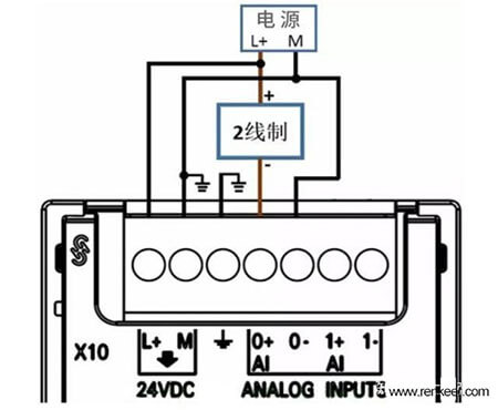
Two-wire system humidity temperature monitor
The two-wire signal means that the signal line and the power line have only 2 lines in the equipment that provides the signal. Since the analog quantity module channel generally has no power supply function, the temperature and humidity sensor instrument or device needs an external 24V DC power supply. The wiring of the two-wire signal is shown in the figure below:
Precautions for wiring of analog temperature and humidity sensor:
1. The sensor cable of the analog signal should be as short as possible. Use shielded twisted-pair cables. Try not to bend at right angles during the wiring process. The shielding layer should be grounded at one end near the signal source.
2. The analog module and sensor should be well-grounded. If possible, the two ground terminals should be connected to the ground. Otherwise, a high common-mode voltage will be generated, which will cause large fluctuations in the data in the CPU.
3. The terminals of the analog module are distributed in two rows, which is easy to be confused. Pay attention when wiring. It is best to connect the lower one first and then the upper one.