The temperature and humidity transmitter refers to a device or device that can convert temperature and humidity into electrical signals that can be easily measured and processed. This device that converts physical quantities into electrical signals is called a transmitter. The most widely used in industry is to use 4 20mA current to transmit analog quantity.
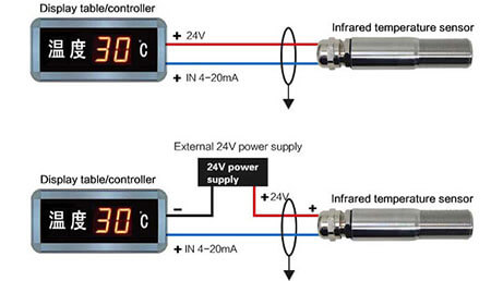
Why use 4-20mA current?
The reason for using the current signal is that it is not easily disturbed. And the internal resistance of the current source is infinite, and the resistance of the wire in series in the loop does not affect the accuracy, and it can transmit hundreds of meters on the ordinary twisted pair. The upper limit is 20mA because of explosion-proof requirements: the spark energy caused by the on-off of the 20mA current is not enough to detonate the gas. The reason why the lower limit is not set to 0mA is to be able to detect disconnection: it will not be lower than 4mA during normal operation. When the transmission line is broken due to a fault, the loop current drops to 0. 2mA is often used as the disconnection alarm value. There are two reasons. One reason is to avoid interference. Another reason is that the 4-20mA uses a two-wire system, that is, the two wires are the signal wire and the power wire at the same time, and 4mA is to provide the static working current of the circuit to the transmitter use.
Interference factors:
1. It is related to the excitation voltage.
2. It is related to the minimum working voltage allowed by the transmitter.
3. It is related to the size of the voltage taking resistor used by the board device to collect current.
4. It is related to the size of the wire resistance. Through these four related quantities, the theoretical transmission distance of 4-20mA current signal can be calculated.
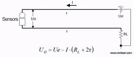
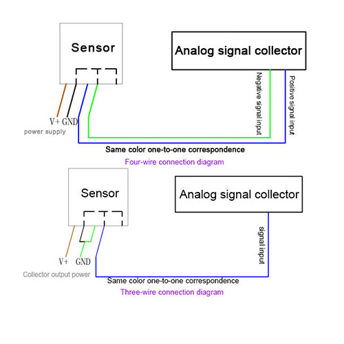
Figure 1: Two-wire transmitter current signal transmission circuit
Among them, Uo is the supply voltage of the transmitter, and it must be ensured that Uo≥Umin at full load (current I=20mA).
which is: According to this formula, the maximum wire resistance can be calculated when the transmitter is at the lowest operating voltage. Assumption:
Known: Ue=24V, I=20mA, RL=250Ω, Umin=12V. Find the maximum value of r as 175Ω:
Then according to the calculation formula of wire resistance, where:
ρ——Resistivity (copper resistivity=0.017, aluminum resistivity=0.029)
L-the length of the line (unit: meters)
S——The cross section of the line (unit: square millimeter)
Note: The resistance value is directly proportional to the length and inversely proportional to the cross-sectional area. The longer the wire, the greater the resistance, and the thicker the wire, the lower the resistance.
Take the copper wire as an example, ρ= 0.017 Ω·mm2/m, that is, the resistance of a copper wire with a cross-sectional area of 1mm2 and a length of 1m is 0.017Ω. Then the wire length corresponding to 1mm2 of 175Ω is 175/0.017=10294 (m).
Therefore, in theory, 4-20mA signal transmission can reach tens of thousands of meters (depending on factors such as different excitation voltages and the lowest working voltage of the transmitter).
So why is the DC voltage signal inappropriate for long-distance transmission?
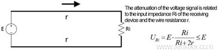
It is described in the standard “GB/T 3369.2-2008 Analog Signals for Process Control Systems Part 2: DC Voltage Signals”: “In contrast to the analog DC current signals specified in GB/T 3369.1-2008, the analog DC signals specified in this part Voltage signals should not be used for long-distance transmission”. The main reason is that the voltage signal will be attenuated after long-distance transmission, and it is easily interfered.
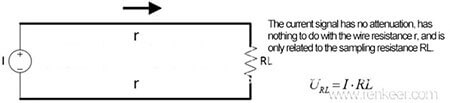
Figure 2: Attenuation during voltage signal transmission