The commonly used communication method for data acquisition and control is RS-485. RS-485 is a general communication standard. It can not only link devices to the local network, but also put multiple 485 devices on the same bus, enabling multiple nodes to link to each other.
What is RS-485?
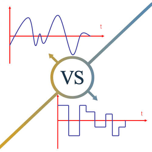
RS-485 (also known as TIA/EIA-485) is a standard interface for physical serial communication. Typical serial communication standards include RS-232 and RS-485, but RS-485 uses differential signaling and supports multi-point networks, unlike RS-232.
RS-485 uses balanced differential signaling, which suppresses common-mode interference. The receiver can detect a differential voltage as low as ±200 mV, allowing signals to be recovered over long distances. RS-485’s main advantage is supporting communication between multiple nodes on the same bus.
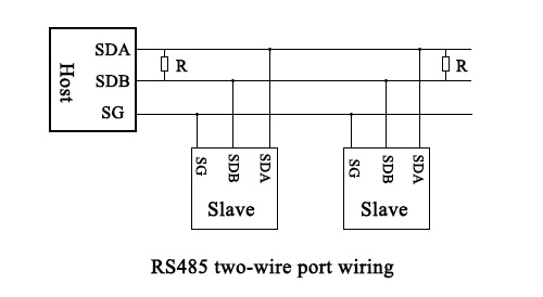
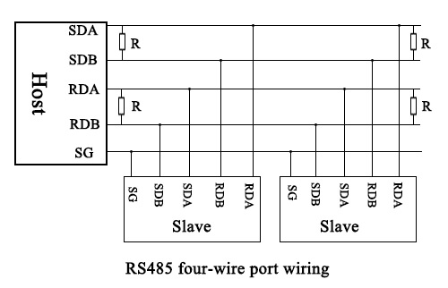
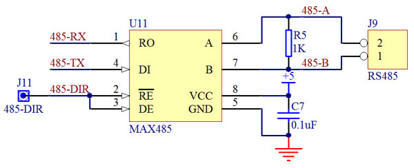
RS-485 wiring methods include two-wire system and four-wire system. Four-wire system can only realize point-to-point communication, which is rarely used now. The two-wire wiring method is mostly used. The two-wire system, arranged in a bus topology, can connect up to 32 standard unit-load nodes on the same bus. The commonly used RS485 circuit is shown in the following figure:
RS-485 features
RS-485 represents logic “1” and ”0” by the polarity of the differential voltage between the two lines. Receivers detect logic correctly when the differential voltage exceeds ±200 mV. Typical driver output may reach several volts, but the standard only specifies the minimum guaranteed differential voltage. This differential level also allows easy interfacing with TTL logic in many circuits.
The RS-485 maximum transmission rate can reach 10 Mbps over short distances, but practical maximum speed decreases as cable length increases.
The RS485 interface is strong, and the anti-noise interference is good.
Under standard conditions, RS-485 can transmit up to approximately 1200 meters, depending on cable type, baud rate, and environmental noise. In addition, the RS-232-C interface allows only one transceiver to be connected to the bus, which is called single-station capability. But the RS485 interface allows up to 128 transceivers to be connected on the bus, with multi-station capability. In this way, users can easily establish a device network through a single RS-485 interface.
RS485 communication principle
The RS485 signal will be decomposed into two lines with positive and negative symmetry (often called A and B signal lines) before transmission. After reaching the receiving end, the two signals are restored to the original signals. In RS-485, a logic “1” or “0” is determined by the polarity of the differential voltage between the A and B lines. The receiver is guaranteed to correctly detect a logic level when the differential voltage is at least ±200 mV, although the actual output swing from modern transceivers may be several volts depending on load and cable conditions. RS-485 drivers also include an “enable” control terminal, which when deactivated, places the driver in a high-impedance state. This high-impedance condition represents a third electrical state, distinct from the logic “1” and logic “0” states, allowing multiple devices to share the same bus without contention.
The transmitter and receiver connect through a balanced twisted pair (lines A and B). The receiver outputs a logic “1” if the differential voltage (A-B) exceeds +200 mV, and outputs a logic “0” if the differential voltage is below -200 mV. While modern drivers may produce a differential swing of several volts, the RS-485 standard only specifies the minimum ±200 mV required for reliable logic detection under standard loading conditions.
For example, to transmit a logic “1”, the driver outputs a higher voltage on line A relative to line B. The receiver measures the differential voltage (A-B) and interprets it as a logic “1”. To transmit a logic “0”, the driver outputs a higher voltage on line B relative to line A, which the receiver interprets as logic “0”. This differential subtraction ensures robust signal detection even in electrically noisy environments.
RS485 wiring
In typical installations, standard twisted-pair cables are sufficient for RS-485 communication. In environments with high electromagnetic interference, shielded coaxial cables or shielded twisted pairs are recommended to minimize noise coupling. The maximum transmission distance of a given RS-485 bus is inversely proportional to the communication baud rate, since higher data rates are more susceptible to signal distortion, reflections, and noise. Engineers must consider cable type, characteristic impedance, and environmental factors when calculating practical line length.
In theory, an RS-485 bus can transmit up to approximately 1200 meters at low baud rates over standard twisted-pair cabling. In practice, environmental noise, cable quality, and network topology reduce the achievable distance, often to around 1000~1200 meters. Signal repeaters can extend the network further; up to eight repeaters may be used under ideal conditions to reach total distances of several kilometers, though exact performance depends on baud rate and cable type. For extremely long distances, optical fiber can be used as the transmission medium with photoelectric converters at the transmitter and receiver. Multimode fiber typically supports 5~10 kilometers depending on fiber and wavelength, while single-mode fiber can extend distances to tens of kilometers, with proper termination and signal conditioning.
After the hardware communication interface is established, a data protocol needs to be agreed between the instruments for data transmission, so that the receiving end can parse the received data, which is the “protocol”. For RS485 signal transmission, the most commonly used communication protocol is Modbus.
What is the Modbus protocol?
Modbus is an internationally recognized serial communication protocol widely used in industrial applications. It allows devices from different manufacturers to exchange information reliably over 485 or other serial links. Conceptually, the protocol acts as a “language” for machines, defining software-level message structures, device addresses, function codes, and cyclic redundancy check (CRC) error detection, enabling standardized communication.
Modbus was introduced in 1979 by Modicon Corporation (now Schneider Electric) to enable communication with programmable logic controllers (PLCs). Over time, it became the de facto standard for industrial serial communication protocols due to its simplicity, widespread adoption, and interoperability between devices from different vendors. The primary reasons for its widespread use include:
- Publicly documented and free of copyright restrictions: Modbus specifications are openly available, allowing manufacturers and developers to implement the protocol without licensing concerns.
- Ease of deployment and maintenance: The protocol has simple addressing, framing, and function code rules, making implementation and troubleshooting straightforward.
- Flexible data handling: Modbus imposes minimal restrictions on how device registers or individual bits are organized, enabling flexible integration with different hardware and software environments.
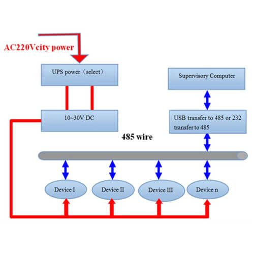
Modbus supports communication among multiple devices on the same network, typically up to 247 nodes on a single segment, depending on device addressing and unit load. For example, a temperature and humidity sensor can transmit measurement data to a central computer, PLC, or data logger. In SCADA (Supervisory Control and Data Acquisition) systems, Modbus is widely used to link a supervisory control computer with remote terminal units (RTUs) or other field devices, enabling centralized monitoring, control, and logging of industrial processes. The protocol ensures reliable data transfer by specifying standardized message framing, device addressing, function codes, and error detection using CRC (cyclic redundancy check).
Modbus functions as a communication protocol, analogous to a language that allows machines to “speak” to each other. The 485 or 232 hardware interface acts as the transmission medium, providing the physical pathway for Modbus messages to travel. A single Modbus protocol can operate over either RS485 or RS232, depending on the network design and distance requirements. However, multiple protocols cannot coexist on the same physical bus simultaneously, as this would cause signal collisions and data corruption. Proper implementation requires that all devices on the bus use the same protocol and adhere to the timing, addressing, and framing rules defined by Modbus.
Difference between RS485 and RS232
RS-232 uses single-ended signaling, meaning the voltage on the data line is referenced to a common signal ground. This unbalanced method is more sensitive to noise and ground potential differences compared to differential signaling. RS-232 was originally designed for point-to-point communication between DTE (Data Terminal Equipment) and DCE (Data Communication Equipment), typically supporting full-duplex transmission with separate transmit and receive lines. While half-duplex operation is possible, it is less common in RS-232 systems due to the standard’s original design.
| RS485 | RS232 |
|---|---|
| Balanced differential transmission | Unbalanced single-ended transmission |
| ~1200 meters (longer with repeaters or low-speed configurations) | ~15 meters (shorter for higher baud rates, rarely exceeding 50 m) |
| 1 to 32 devices per bus segment (multi-drop) | Point-to-point, 1 to 1 connection |
| Differential: A-B ≥ +200 mV = logic 1; A-B ≤ -200 mV = logic 0; typical driver output 1.5-5 V differential | Logic 1: -3V to -15V; Logic 0: +3V to +15V |
| 2-wire half-duplex (4-wire full-duplex also possible) | 3 wires: transmit, receive, ground |
| Up to 10 Mbps (short cables); typical long-distance operation ≤ 1 Mbps | Up to 115.2 kbps for standard cables; lower for long distances |
1. Transmission distance
RS-232 is limited in communication range due to its single-ended signaling and susceptibility to noise. Standard RS-232 cables can transmit reliably up to approximately 15 meters at 19.2 kbps, and practical installations rarely exceed 50 meters without signal conditioning. In contrast, RS485 supports significantly longer distances due to its differential signaling, with reliable transmission up to approximately 1200 meters at lower baud rates. Using repeaters or low-baud configurations can extend this distance further under controlled conditions.
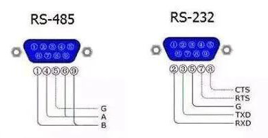
2. Different signal lines
RS-232 typically uses three wires: a transmit line, a receive line, and a common ground, with each data signal referenced to ground. RS-485 generally uses a two-wire differential pair (A and B), where the transmitter sends complementary signals across the pair. The receiver reconstructs the original data by measuring the voltage difference between A and B. This differential approach allows RS485 to cancel common-mode noise and maintain signal integrity over much longer distances than RS-232. While RS-232 may be limited to tens of meters, 485 can achieve distances up to approximately 1200 meters under standard operating conditions, with proper cabling and termination.
3. Maximum baud rate
RS-232 can operate at various baud rates depending on cable length and electrical conditions. While early RS-232 systems were limited to 19.2 kbps over standard cables, modern short-range implementations can reach 115.2 kbps or higher. RS-485 supports much higher data rates, theoretically up to 10 Mbps over short cables, though practical maximum speed decreases as cable length increases. It is mostly used in engineering control signal transmission.
4. Electrical signal technology
The electrical signal technology is an important parameter to judge the anti-noise ability of the two protocols. Using single-ended lines or unbalanced signals in RS232 reduces the standard’s noise immunity to disturbances such as ground loops. RS-485 offers higher noise immunity because it uses balanced differential signaling technology, providing the user with common-mode noise cancellation.
5. Equipment quantity
RS-232 is a point-to-point standard, allowing connection between only two devices per link. RS-485, on the other hand, is designed for multipoint communication, supporting multiple drivers and receivers on the same bus.
6. Network complexity
Connecting multiple devices increases network complexity. RS-232 is easier to implement because there are fewer receivers and drivers to deal with. This is indeed a simple and cheap solution.
Quick FAQs
Is RS485 a communication protocol?
No. It only defines electrical and physical layer characteristics such as voltage levels and differential signaling. It does not define data formats, addressing, or error checking. Protocols like Modbus RTU operate on top of RS485.
Does RS485 support full-duplex communication?
Yes. it can operate in half-duplex mode using a 2-wire configuration, or in full-duplex mode using a 4-wire configuration with separate transmit and receive pairs.
Why are termination resistors needed in RS485 networks?
Termination resistors, typically 120 Ω, are used to match the cable impedance and prevent signal reflections. They should be installed at both physical ends of the bus, especially for long cables or higher baud rates.
What cable type is recommended for RS485?
Shielded twisted-pair cable is strongly recommended. Twisting improves differential noise rejection, while shielding helps reduce external electromagnetic interference in industrial environments.
Can RS-485 be used outdoors or in harsh environments?
Yes. It is widely used in outdoor and industrial environments such as water quality monitoring, meteorological stations, and energy systems, provided that proper grounding, shielding, and surge protection are implemented.
How should RS485 biasing be implemented for long-term stability?
Bias resistors (pull-up on A, pull-down on B) ensure the bus rests at a defined idle state when no driver is active. Typical values are 390-680 Ω, but must be calculated based on bus unit load and total termination resistance. Excessive biasing can reduce voltage swing and increase power dissipation; insufficient biasing may cause undefined idle states and communication errors.
How do reflections affect 485 networks and how can they be mitigated?
Reflections occur when cable impedance mismatches exist, particularly with stubs or star topologies. They manifest as signal overshoot or ringing. Mitigation strategies include:
- Using a linear daisy-chain topology
- Matching termination resistors to cable characteristic impedance (≈120 Ω)
- Minimizing stub lengths (<0.3 m)
- Using low-capacitance cables for high-speed signals
How does ground potential difference between nodes affect RS-485?
RS-485 can tolerate common-mode voltage differences from -7 V to +12 V. Exceeding this can damage transceivers. Isolation using opto-isolators or isolated 485 transceivers is recommended in environments with large ground potential differences, such as substations or outdoor industrial sites.
What are the effects of termination resistor placement errors?
Placing termination resistors in the wrong location or using incorrect values can cause:
- Signal reflections
- Increased jitter and bit errors
- Unstable logic levels at idle
Best practice: place resistors at the two physical ends of the main bus, not on each node. Use combined resistance of 100~120 Ω matching the cable.
How should RS485 be protected from surges and lightning?
Industrial networks are vulnerable to:
Lightning-induced transients
Switching surges
Protection techniques include:
TVS diodes or surge suppressors on A/B lines
Galvanic isolation between transceivers and system ground
Shielded twisted pair cables grounded at one end to reduce EMI coupling
How do 485 transceiver unit loads affect network design?
A unit load defines how much electrical load a device places on the bus. Standard 485 devices are 1 unit load, but modern transceivers can be 1/4 or 1/8 unit load. Using fractional loads allows more nodes per segment, but increases design complexity for biasing and termination calculations.
How to troubleshoot intermittent RS-485 errors?
- Check termination and bias resistors
- Inspect cable quality (twist, impedance, shielding)
- Verify driver enable logic to prevent bus contention
- Measure differential voltage at the receiver; should be ≥200 mV
- Use isolated transceivers if ground loops or potential differences exist
- Monitor network traffic timing to ensure protocol compliance
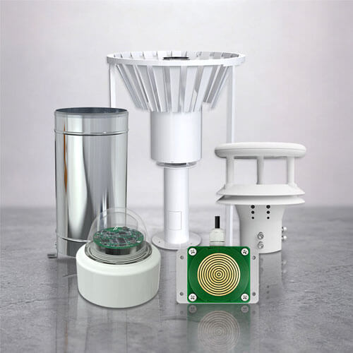
This article is written by the Renke Technical Team. Our engineers work daily with RS-485 based sensing systems, including temperature and humidity sensors, weather instrumnts, and water quality sensors. This extensive field exposure provides our team with deep practical expertise in bus topology design, cabling best practices, termination, noise immunity, and multi-node network architecture. With over 100 products utilizing RS-485 as the primary communication interface, Renke delivers firsthand manufacturing experience and application knowledge that goes far beyond theoretical concepts. For technical consultations or customized RS-485 sensor solutions, please contact us.