What is Modbus?
Modbus is a serial communication protocol used for communication with Programmable Logic Controllers (PLCs). Because of its open protocol and simple deployment, it has become a simple protocol widely used in the industry. It is one of the RS485 communication port protocols
In communication between our microcontrollers or between a microcontroller and a host computer, different content protocols are defined. Both communicating parties need to adhere to this protocol in order to establish communication. There can be multiple protocols to accommodate the communication requirements between different devices. Some common protocols include I2C, SPI, and UART serial communication protocols.
Modbus protocol development
The Modbus protocol was designed and developed by Modicon (now owned by Schneider Electric) in 1979. Since its introduction, it has gained popularity as a standard communication protocol in industrial systems due to its simplicity and openness. It was the first truly fieldbus protocol used in industrial applications worldwide.
To further promote and drive the adoption of Modbus for distributed applications based on Ethernet (TCP/IP), Schneider Electric transferred the ownership of the Modbus protocol to the Interface for Distributed Automation (IDA) organization. They also established the Modbus-IDA international organization, responsible for promoting the Modbus standard and certifying products.
You can find related protocol documentation and manufacturers on the official website at www.modbus.org.
Advantages of Modbus
- The protocol standard is open, publicly available, and has no copyright requirements.
- The protocol supports multiple electrical interfaces, including RS232, RS485, TCP/IP, and can be transmitted over various media such as twisted pair cables, fiber optics, infrared, and wireless.
- The protocol’s message frame format is simple, compact, and easy to understand. It is user-friendly and easy for manufacturers to develop and integrate, facilitating the formation of industrial control networks.
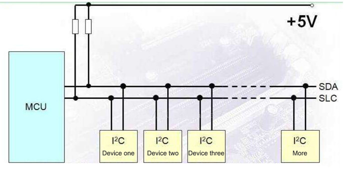
For example, let’s consider the I2C communication protocol, which requires physical connection to the I2C bus. It also requires pull-up resistors and defines the high and low voltage levels at the physical layer. In contrast, the Modbus protocol is an application-layer message transfer protocol that does not define the physical layer. It defines the message structure that controllers can understand and use, regardless of the network used for communication. This flexibility allows Modbus to adapt to multiple electrical interfaces, resulting in its widespread usage.
Modbus terminology
- Master: master station equipment
- Slave: slave device
- Server: server side
- ADU: Application Data Unit
- PDU: Protocol Data Unit
- MSB: Most Significant Bit
- LSB: Least Significant Bit
- MBAP: Modbus Application Protocol
- PLC: Programmable Logic Controller
Serial link protocol
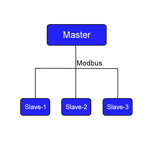
The Modbus serial line protocol operates in a master-slave mode and uses half-duplex data transmission. The RS485 standard typically requires two lines, and at a specific time, there is communication between one master and multiple slaves.
Master-slave mode: Typically, there is one master and multiple slaves on the bus. Each slave has a unique ID, and the master identifies and communicates with the slaves using their IDs for data transmission.
Half-duplex transmission: In contrast to half-duplex, full-duplex allows simultaneous transmission and reception of data. Therefore, in half-duplex mode, data can only be sent or received at any given time.
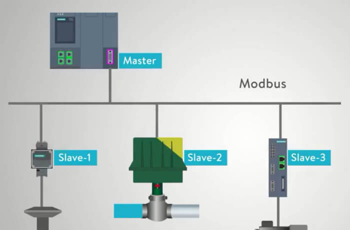
Additionally, slaves cannot initiate communication with other slaves. Only when the master sends data to a slave (sending a request), the slave receives the data from the master and then responds with data. The diagram below illustrates this:

Communication process
In Modbus communication, only one device can send a request. The slaves receive data from the master and respond accordingly. Slaves are peripheral devices such as temperature and humidity sensor, controller, smoke detector, water level sensor, or other types of measurement devices. The slaves process the information and send their data back to the master. Slaves do not initiate communication with the master, they can only reply to messages sent by the master.
Additionally, there is no built-in mechanism in the communication process to determine if a device is busy. For example, if the master sends a command to a slave, but the slave either hasn’t received it or is busy processing other tasks, it cannot respond to the master. Since the RS485 bus is solely responsible for data transmission and lacks additional processing mechanisms, it is necessary to use software-based approaches to determine if the data reception is successful.
Modbus protocol types
The main protocol types include ASCII, RTU (Remote Terminal Unit), and TCP.
- Modbus RTU (Remote Terminal Unit): This mode often uses RS-485 as the physical layer and typically utilizes the serial port of a chip for data message transmission. The message data is communicated in binary format.
- Modbus ASCII: Messages are transmitted using ASCII characters. The ASCII format uses vertical redundancy check (VRC). Modbus ASCII messages start with a colon (“:”) and end with a carriage return/line feed (CR/LF) sequence.
- Modbus TCP/IP or Modbus TCP: This is a variant of Modbus that uses TCP/IP network for communication and connects through port 502. In Modbus-TCP, the message checksum calculation is not required because the Ethernet layer already implements CRC32 data integrity.
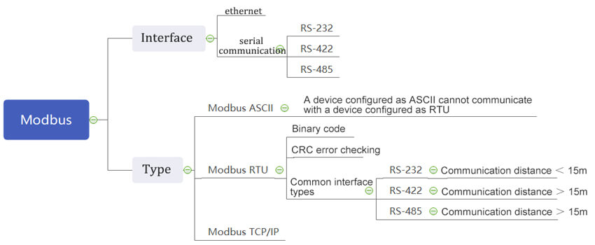
When using serial communication for the Modbus protocol, you can choose between RTU or ASCII modes. Both modes have defined message and data structures, command and response formats, and require data validation. ASCII mode uses Longitudinal Redundancy Check (LRC) for data validation, while RTU mode uses a 16-bit CRC (Cyclic Redundancy Check). When transmitting Modbus over Ethernet using TCP/IP, data is encapsulated within TCP packets. In this mode, checksum validation is not necessary because TCP is a reliable, connection-oriented protocol that already provides data integrity checks.
1. Modbus-RTU protocol
Modbus-RTU is a compact format that represents data in hexadecimal. In the RTU format, each command is followed by a cyclic redundancy check (CRC) checksum. For example, if we need to send the number 10, in RTU mode, we would only need to send 0x0A. The data transmission on the bus would be represented as: 0000 1010.
The frame structure for Modbus messages
A message refers to a single frame of data, and a data frame represents a single message. It refers to a complete set of instruction data and essentially represents a sequence of data. A Modbus message refers to a frame of data that the master sends to the slave. It includes the slave’s address, the operation the master wants to perform, checksum, and other relevant information.
The message format for Modbus protocol on a serial link is as follows:
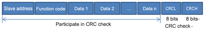
| Slave address | Function code | Data | CRC/LRC |
|---|---|---|---|
| 1 byte | 1 byte | N bytes | 2 bytes |
- Slave Address: Each slave device has a unique address, occupying one byte, with a range of 0-255. The valid range for slave addresses is 1-247 because 255 is reserved for the broadcast address (broadcasting a message to all slave devices).
- Function Code: Occupying one byte, the function code indicates the purpose of the instruction. For example, you can use function codes to query data from a slave device or modify data on a slave device. Different function codes correspond to different functionalities.
- Data: The data portion varies depending on the function code. For example, if the function code is used to query data from a slave device, the data may include the address to query and the number of bytes to read.
- Checksum: During data transmission, errors may occur. The checksum, such as CRC, is used to verify the correctness of the received data.
Modbus function code
Modbus protocol defines multiple functions, and to conveniently utilize these functions, each function is assigned a function code, which acts as a code or identifier. The protocol specifies over twenty function codes, but there are commonly used 8 function codes that are used for reading and writing to storage areas. Here is a table illustrating these common function codes:
| Function code | Function Description |
| 01H | read output coil |
| 02H | read input coil |
| 03H | read holding register |
| 04H | read input register |
| 05H | write single coil |
| 06H | write single register |
| 0FH | write multi-coil |
| 10H | write multiple registers |
CRC check
CRC (Cyclic Redundancy Check) is an error-checking mechanism used in Modbus protocol. The CRC field occupies two bytes and contains a 16-bit binary value. The CRC value is calculated by the transmitting device and appended to the data frame. The receiving device recalculates the CRC value upon receiving the data and compares it with the CRC field value in the received frame. If the two values do not match, an error has occurred.
For example, if the master sends the frame 01 06 00 01 00 17 98 04, where 98 04 represents the CRC field, the slave device needs to recalculate the CRC value based on the data portion 01 06 00 01 00 17. The slave then compares the calculated CRC value with the received CRC value (98 04, calculated by the master). If the values do not match, it indicates a data transmission error, and the data cannot be considered valid.
The CRC (Cyclic Redundancy Check) validation process can be summarized as follows:
- Initialize a 16-bit register with the value 0xFFFF (all bits set to 1). This register is known as the CRC register.
- XOR the first byte (8 bits) of the data frame with the low byte of the CRC register, and store the result back in the CRC register.
- Right-shift the CRC register by one bit. Fill the highest bit with 0 and check the lowest bit that is shifted out.
- If the lowest bit is 0, repeat step 3 (shift again); if the lowest bit is 1, XOR the CRC register with a predetermined fixed value (0xA001).
- Repeat steps 3 and 4 for a total of 8 shifts. This completes the processing for one complete 8-bit segment.
- Repeat steps 2 to 5 for the next octet until all bytes have been processed.
- The final value of the CRC register is the calculated CRC value.
Modbus-ACSII protocol
Modbus-ASCII is a representation format where data is expressed using ASCII codes, and each 8-bit byte is transmitted as two ASCII characters. The ASCII format uses longitudinal redundancy check (LRC) as the checksum.
For example, if we need to send the number 10, in ASCII mode, we would convert the digits ‘1’ and ‘0’ to their ASCII representation. So, we would send the bytes 0x31 (ASCII code for ‘1’) and 0x30 (ASCII code for ‘0’). The data transmission on the bus would be represented as: 0011 0001 0011 0000
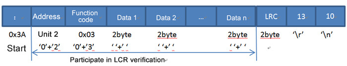
The Modbus-ASCII message frame structure
- Start Bit: 1 byte indicating the start of the message frame.
- Address Bits: 2 bytes representing the address of the slave device.
- Function Bits: 2 bytes specifying the function code indicating the operation to be performed.
- Data Bits: n data bits, least significant bit sent first
- LRC (Longitudinal Redundancy Check): Unlike CRC, Modbus ASCII mode uses LRC for error checking. LRC is calculated over the ASCII representation of the address, function, and data bytes.
- Terminator: The message frame is terminated by the characters \r (carriage return) and \n (line feed), indicating the end of the message.
In Modbus-ASCII, there are start and end characters (CR LF) that serve as indicators for the beginning and end of a data frame. On the other hand, Modbus-RTU does not have such markers and relies on timing intervals to determine the start and end of a frame. The protocol specifies a time duration of 3.5 character periods. This means that before the start of a frame, there must be an idle time greater than 3.5 character periods, and after the end of a frame, there must also be an idle time of 3.5 character periods to avoid packet overlap or “glitch” situations.
Note: The 3.5 character periods represent a specific time duration, but it is dependent on the baud rate. In serial communication, 1 character typically consists of 1 start bit, 8 data bits (in most cases), 1 parity bit (or none), and 1 stop bit. Thus, 1 character comprises 11 bits. Therefore, 3.5 characters correspond to 38.5 bits. The meaning of the baud rate is the bit of the binary bit transmitted per second. So, for a baud rate of 9600, 3.5 characters = 9600 / 38.5 = 0.00401s * 1000 = 4.01ms.
Modbus-TCP protocol
Modbus-TCP does not need the slave address, but the MBAP header. And it does not require error-checking because TCP itself has error-checking capabilities.
The MBAP header
| Area | Length | Describe | Client computer | Server |
|---|---|---|---|---|
| Transaction identifier | 2 bytes | Identification of Modbus request/response transactions | client start | The server re-copied from the received request |
| Protocol identifier | 2 bytes | 0=Modbus protocol | client start | The server re-copied from the received request |
| Length | 2 bytes | the number of bytes that follow | client start(request) | server(response) start |
| Unit identifier | 1 byte | Identification of remote slaves connected on a serial link or other bus | client start | The server re-copied from the received request |
In simple terms, Modbus-TCP is derived from Modbus-ASCII but removes the checksum verification and adds five bytes of zeros followed by a single byte with the value 0x06.