In the fields of electrical engineering and electronics, we frequently encounter various analog signals such as voltage and current. In nature, analog signals are even more abundant, including temperature, wind speed, pressure, humidity, and pH levels. But how exactly is an analog signal defined? This article will provide a detailed explanation of the definition, types, applications of the analog signal, and how it differs from the digital signal.
What is an analog signal?
An analog signal is a continuous electrical signal that represents a measured variable. It can be based on either voltage or current, and its amplitude is scaled according to the range of the measured parameter. Analog signals can be compared to a dimmer switch for a light bulb—when you adjust the dimmer, the brightness of the light changes smoothly and continuously.
Most physical quantities in the real world change in a continuous manner and can be divided almost infinitely in both time and space. Take temperature as an example: over a continuous period, the temperature has a specific value at every moment, no matter how infinitesimally small that moment is. Such uninterrupted and continuous signals are referred to as analog signals. Of course, the term “infinitesimally small” here is a conceptual ideal—in the physical world, achieving such infinite precision is practically impossible.
What are the standard analog signals?
Most sensors use one of the following two types of analog signals: analog voltage (typically 0-10 V, sometimes 0-5 V) or analog current (commonly 4-20 mA).
Voltage signals
0-5V: This is a common form of analog voltage output, representing a measured parameter that varies from 0 to a maximum of 5 volts. It is suitable for short-distance transmission and is widely used in low-voltage control systems, embedded devices, and data acquisition modules.
0-10V: This analog voltage signal offers a wider range, allowing for the representation of larger variations in analog quantities. In this case, 0V corresponds to the lower limit of the measurement range, while 10V corresponds to the upper limit. Compared to 0-5V, it provides higher resolution for more precise measurement.
Current signal
4-20mA: This is an analog signal widely used in industrial control systems, especially for situations where long-distance transmission and signal stability are required. This is because current signals are less susceptible to line resistance during transmission than voltage signals. Among them, 4mA represents the lower limit of the measurement range and 20mA represents the upper limit of the measurement range. Using 4mA instead of 0mA as a starting point is to increase the system’s “fault detection” capability. In most cases, the current output signal is powered by a 24 volt DC power supply.
Difference between 4-20mA, 0-10V and 0-5V
Both 0-5V and 0-10V are analog signals with voltage output, whereas 4-20 mA is an analog signal with current output.
The 0-5V signal is a low-voltage, linear analog output commonly used in embedded systems, low-power and short-distance local measurement systems. Most microcontrollers(such as STM32, Arduino, and ESP32) as well as low-voltage data acquisition cards, have an ADC input range of 0-5V. This allows direct connection without the need for signal conditioning, isolation, or sampling conversion, reducing peripheral circuitry and improving development efficiency.
As one of the simplest and most fundamental analog transmission methods, the 0-10V signal is widely used in HVAC applications. It offers reliable performance, is easy to troubleshoot, and is accepted by nearly all industrial controllers. Compared to 0-5V, the 0-10V signal provides twice the resolution at the same ADC precision level, allowing for finer detection and control of signal variations.
However, they also have disadvantages:
- Voltage signals are highly susceptible to electrical noise and interference.
- Sensors require a third wire to power the device, separate from the two signal wires.
- Long cable lengths can cause voltage drop, leading to reduced accuracy.
- A 0V value cannot distinguish between a zero measurement and no signal, making sensor faults difficult to detect.
With the advancement of industrial sensors and automation systems, the 4-20 mA current signal has become increasingly common. Although current signals cannot be directly connected to the MCU’s ADC (analog to digital converter) and require additional components such as a sampling resistor (e.g., 250Ω) and amplification/isolation circuits, they are generally more reliable and convenient for the following reasons:
- Current signals are less susceptible to noise, interference, or voltage drops.
- Only two wires are needed. Since there is always at least 4mA flowing in the loop, instruments can be powered via “loop power” using the same two wires that carry the signal.
- Long cables do not affect the accuracy of current signals.
- Fault detection is straightforward. A reading of 0mA indicates no signal, while 4mA corresponds to a zero measurement value.
Analog signal vs. Digital signal
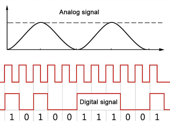
An analog signal is a continuously varying physical signal—such as voltage, current, or frequency—that can take any value within a given range. In contrast, a digital signal transmits information using discrete binary values(typically 0 and 1). Digital signals do not represent continuous changes in levels but encode, transmit, and decode information through transitions between “high” and “low” states.
For example, consider controlling a light: an analog signal is like a dimmer knob that allows you to gradually adjust the brightness from slightly dim to very bright, offering multiple levels of intensity. But a digital signal is like a simple on/off switch with only two states, either fully on or fully off. The analog signal provides a continuum of options between these extremes.
Which is better? In some ways, that depends on what you want to do. Digital signals are typically easier and less error-prone to copy. Anything that interferes with an analog signal becomes part of the signal, and can be very difficult to remove. With digital signals, only the things you’ve defined to be part of the description actually matter, so interference is usually easier to spot, and then you can ignore it or correct it. Digital signals are rarely perfect, descriptions can only go into so much detail, but because of the interference problem, analog signals aren’t usually perfect either. The interference problem becomes a big issue for copying analog signal, because imperfections in the machinery add up over time, while those imperfections generally don’t matter for digital signals anyway.
What are the applications of analog signal?
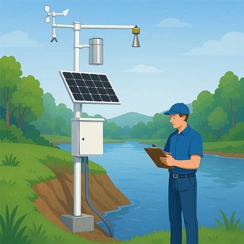
In the industrial field, people often use various sensors to realize functions such as analog signal acquisition and conversion. What are the common instruments and meters in industrial sites?
This is a device that converts pressure into pneumatic or electric signals for control and remote transmission. The most common one is the electric signal. It can convert the gas or liquid pressure felt by the pressure measuring element into a standard analog signal (such as 4~20mA current signal, 0-5V/0-10V voltage signal) to supply secondary instruments such as indicator alarms, recorders, and regulators for adjustment.
Temperature sensor
The temperature sensor uses thermocouples and thermal resistors as temperature measuring elements. The temperature measuring element outputs the signal to the transmitter module. After the signal is processed by circuits such as voltage stabilization and filtering, operational amplification, nonlinear correction, V/I conversion, constant current and reverse protection, it is converted into an analog signal that is linearly related to the temperature.
pH sensors use the potential difference measured by the glass electrode to reflect the concentration of hydrogen ions in water. The potential value is linearly related to the pH value of water (about 59.16mV per pH unit change at 25°C). Through the electrochemical cell formed with the reference electrode, the tiny millivolt signal is extracted and converted into an analog voltage signal (generally within the range of ±414mV) that is easier to collect after being processed by a high input impedance amplifier. This continuous output is the analog signal representing the pH change.
The liquid level sensor is based on the principle that the static pressure of the liquid is proportional to the liquid level. The sensor mostly uses a piezoresistive strain gauge. The static pressure exerted by the liquid causes the sensitive diaphragm to deform slightly, which in turn causes the strain resistance value to change. This signal is amplified, temperature compensated and linearly conditioned, and converted into an analog signal.
The gas detector is a device that measures the concentration of a single or multiple gases. There are two main types of gas detectors: catalytic and infrared optical. Catalytic gas detectors use the resistance change of refractory metal platinum wire after heating to measure the concentration of combustible gas.