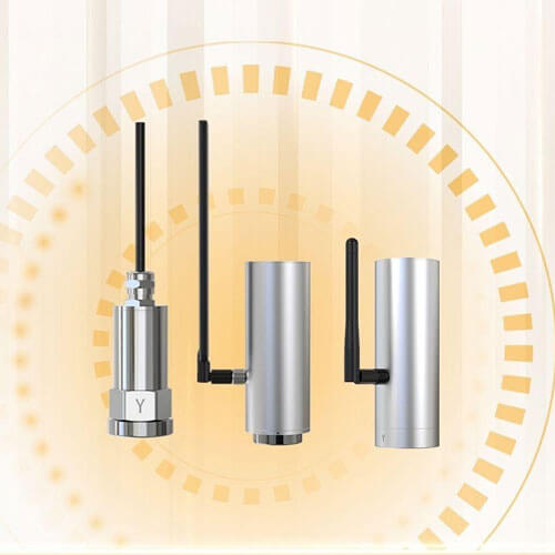
In industrial applications, motors serve as the primary driving force behind a wide range of machinery. Any malfunction can result in production downtime and significant losses. According to data from the Electric Power Research Institute (EPRI) and the Construction Specifications Institute (CSI), implementing condition monitoring and fault diagnostics for electrical equipment can increase equipment utilization by 2%-10%, extend service life by 10%-15%, and reduce maintenance costs by 25%-30%. Achieving these benefits relies heavily on real-time monitoring of equipment temperature and vibration. Variations in temperature and vibration are key indicators of potential faults, if not detected promptly, they can escalate into major issues that disrupt production.
With the advancement of automation, vibration monitoring has become a core component of modern industrial equipment management systems.
However, a common challenge in today’s vibration monitoring devices is their limited frequency response range. These limitations make them susceptible to Nyquist-related constraints and aliasing effects, which can distort measurement data and hinder accurate, comprehensive assessment of a machine’s actual operating condition.
What are the Nyquist Frequency and Aliasing?
The Nyquist frequency is defined as half of the sampling rate and determines the upper limit of measurable frequency content. When high frequency harmonics exceed the Nyquist frequency, aliasing occurs. These high frequency components are incorrectly folded back into the lower frequency range, contaminating the usable measurement data.
For example, although the main shaft of a conveyor motor may operate at only 100-200 Hz, this does not mean that a vibration sensor with a 10-1600 Hz frequency range is sufficient. Mechanical resonance and high frequency harmonics generated during motor operation can trigger aliasing, causing high frequency components to be folded into the measurable band. This leads to distorted and unreliable vibration data.
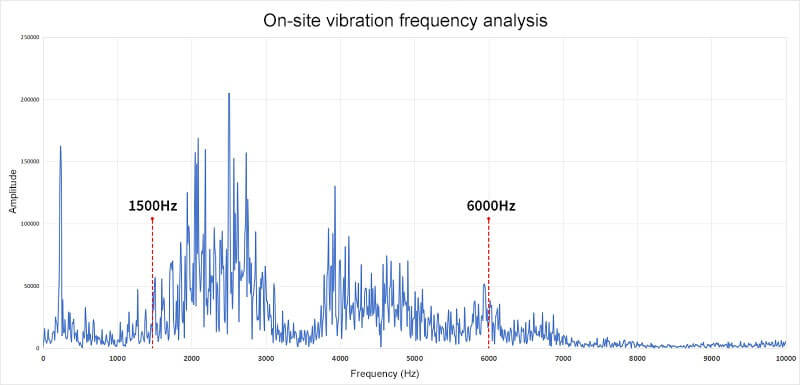
The data chart is from actual measurements on Renke’s customer production line.
The figure above shows vibration monitoring data collected from a Renke customer’s motor during operation. As shown, the motor’s main shaft frequency is 60 Hz, corresponding to a rotational speed of approximately 3600 r/min, which falls within a relatively low frequency range. Although there is some amplitude response below 100Hz, the energy is much more concentrated between 1500 Hz and 6000 Hz.
If a user were to select a conventional vibration monitoring device with a maximum frequency response of only 1600 Hz, the high frequency harmonics exceeding the Nyquist limit would be folded back into the lower frequency band. This produces false frequency components (aliasing), directly affecting the accuracy of the vibration monitoring sensor’s output. Even the higher-end vibration monitoring devices currently available on the market, which offer up to 5000 Hz of frequency response, are still insufficient based on the distribution shown in the collected data.
Why is a 12,000 Hz vibration monitoring sensor superior?
To address the common limitations of conventional vibration monitoring devices, particularly their restricted frequency response. Renke conducted in-depth research and systematic analysis of customer requirements. Based on these findings, we optimized and upgraded our standard temperature vibration sensors and introduced a new transmitter with a frequency response range of 10-12,000 Hz.
A 10-12,000 Hz frequency response range enables comprehensive coverage of the vibration frequencies generated during mechanical operation. It captures both the high frequency vibrations produced by fast-rotating components and the characteristic frequency signals that indicate early-stage faults. This wide bandwidth eliminates the risk of missing critical information caused by limited frequency range.
Furthermore, the 10-12,000 Hz capability significantly reduces aliasing associated with the Nyquist limit, ensuring data accuracy and measurement integrity. This provides a solid foundation for timely fault detection and precise diagnostics, supporting the shift from reactive maintenance to proactive monitoring. It is a key technology for maintaining stable and efficient industrial operations.
Why monitor the surface temperature of equipment?
During operation, mechanical equipment generates heat due to friction, overload, poor lubrication, or internal faults. This heat often appears as an abnormal rise in surface temperature, making temperature one of the most accessible and informative indicators of equipment health. Issues such as bearing lubrication failure, misalignment, or abnormal loading typically cause temperature changes before noticeable vibration occurs, making temperature monitoring essential.
As shown in the on-site data collected from Renke customers, the surface temperature of mechanical equipment can gradually rise to high levels during continuous operation, for example, reaching 58.4°C in the measured case. Such elevated temperatures are common in real industrial environments. Conventional vibration monitoring devices often have limited temperature resistance and can suffer from reduced accuracy, data interruptions, internal component damage, or even complete failure when exposed to high temperatures.
Renke’s vibration monitoring sensors are designed to address these challenges. Our temperature vibration sensors can operate reliably in environments up to 80°C, and higher temperature ratings are available upon request, making them suitable for a wide range of demanding industrial conditions. They also support direct surface temperature monitoring, with high temperature versions covering a measurement range of -40°C to 150°C. Continuous temperature tracking enables users to detect anomalies promptly, assess operating conditions, identify emerging faults earlier, and extend equipment service life.
Beyond frequency range and temperature resistance, we have also enhanced our devices to overcome additional common challenges in vibration monitoring, such as limited accuracy, single-direction measurement, low protection grade, data transmission constraints, and difficult installation. Our goal is to provide robust, comprehensive technical support to ensure the safe, stable, and efficient operation of mechanical equipment.
Advantages and application cases of Renke vibration monitoring sensors
Compared with conventional vibration monitoring sensors, Renke’s temperature and vibration sensors with a frequency response range of 10-12,000 Hz, which can accurately capture the full vibration spectrum of equipment, from low-speed gearboxes to high-speed bearings. Equipped with MEMS chips and high sensitivity sensing elements, they achieve vibration RMS measurement accuracy of <1%, while offering a wide temperature monitoring range from -40°C to 150°C.
Our sensors use high-performance MEMS technology. Compared with traditional sensing components, MEMS chips offer inherent advantages such as compact size, low weight, and minimal power consumption, while maintaining stable performance in harsh environments. Their finely structured internal design enables precise conversion of mechanical vibration into electrical signals, delivering high-fidelity data for downstream diagnostics. The system can detect extremely small vibration amplitudes, capturing subtle early-stage fault signatures that conventional sensors often miss. This allows engineers to intervene before a minor defect escalates into a severe equipment failure. Renke’s temperature and vibration sensors have already demonstrated outstanding results across numerous real-world applications.
Application case 1
At the Shougang Qian’ an Steel rolling production line, the customer deployed 32 of our vibration monitoring systems to track the operating condition of 725 drive shafts. The system successfully issued early warnings for 17 bearing faults. In one notable case, the vibration monitoring system detected an 8,000 Hz high frequency harmonic and predicted a pitting fault in a high speed gearbox 83 hours in advance, preventing a potential unplanned shutdown that could have resulted in RMB 3.6 million in losses.
Application case 2
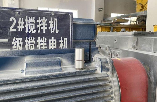
The temperature and vibration sensors used in our monitoring system feature IP67 protection and explosion-proof certification. Their housings are made of solid stainless steel or die-cast aluminum, and they maintain full scale accuracy even after -40°C thermal shock testing. In the Guangdong Yuehua Steel Phase III project, Renke sensors operated continuously for eight months in high temperature quenching workshops, achieving zero failures across 72 monitoring points.
Application case 3
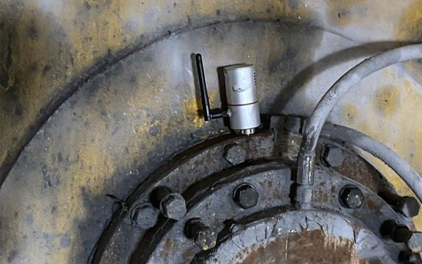
In the Baosteel Zhanjiang Phase II project, our vibration monitoring equipment withstood 6,000 hours of heavy dust exposure, maintaining data drift within just 0.1%. The system achieved 250 consecutive days of maintenance free operation in the steelmaking workshop. This exceptional environmental resilience ensures long-term stable performance under extreme industrial conditions.
Application case 4
In the Phase III project of Shandong Energy Group in the Northwest region, Renke’s temperature and vibration sensors delivered significant value through highly accurate predictive maintenance. More than 100 sensors were deployed across the production line, enabling 24/7 continuous condition monitoring. Over an 11-month period, the system achieved a 99.95% data acquisition integrity rate and successfully issued 27 early warnings for potential faults. As a result, unplanned downtime related to critical infrastructure was reduced by 73%, average fault response time decreased by 85%, and an estimated RMB 4 million in potential losses was avoided. This case demonstrates the technology’s outstanding performance in enhancing both operational safety and economic efficiency.
When is a 12,000 Hz vibration sensor the better choice?
In most cases, or for basic vibration velocity measurements, monitoring devices with a frequency range of 10-1600 Hz or 10-5000 Hz are usually sufficient. However, sensors with a 10-12,000 Hz frequency response are designed for applications requiring high frequency vibration analysis. They are ideal for scenarios such as:
1. High-speed rotating machinery including motors, turbines, and compressors operating above 10,000 RPM. These devices can accurately capture high frequency vibration signatures related to bearing defects, gear mesh abnormalities, and other critical issues.
2. CNC machines and precision spindles, where high frequency vibration monitoring prevents machining accuracy loss, tool wear, and surface defects. This is especially beneficial for detecting micron-level vibration anomalies.
3. Aerospace components, such as aircraft engines and helicopter rotors, where high frequency analysis helps identify early fatigue cracks, structural resonance, or imbalance.
4. Impact-intensive equipment, including stamping and forging machinery, where monitoring transient high frequency shocks helps determine whether instantaneous loads exceed safe.